Overclocking the Acorn A7000+ - How To Do It
Necessary Precautions
Practice your soldering skills on an old junk PCB first, especially if it has an oscillator like the one in the Acorn - they will not come out as easily as most electronic components (e.g. capacitors, diodes, etc.) after desoldering. Care in removing them must be taken.
Before doing ANY [de]soldering, cover up ALL the tracks under the PCB that lie close to the four solder points which hold in the legs of the target oscillator - something like electrical tape should work great for this purpose.
Can the standard Acorn A7000 be overclocked with this guide?
Given that it does have the solder points for an oscillator (or socket) available below the CPU (picture can be found here), it MAY be possible. But I haven't got one, so I couldn't possibly verify this. If you wish to use this guide with your Acorn A7000, though, you do so at your own risk - that said, it'd be easier, as you wouldn't have to spend time removing the old oscillator. I don't know if anything else would have to be changed though, e.g. jumpers on the board.
Tools
- Soldering iron (anything from 15-25W will be fine)
-
Desoldering braid (the stuff I get is called Servisol Soldamop, and it works fine)
-
60%-to-40% solder (referring to the tin-to-lead mixture), if possible - otherwise, get lead-free solder, however it's not as good (but much more common).
- Electrical tape
-
Soldering flux - I know what you're going to say, "but most solder already has flux in it!". That's true, but having the extra flux definitely helps out. To use it, just dab a little bit on the solder before you melt it onto whatever you want to solder in - it will make the job much easier.
- Anti-static wrist strap - just in case. Better to have one than not.
Availability: Maplin should stock all of this except for the flux, which can be bought from B&Q (UK).
Components
-
An 8-pin DIL socket
-
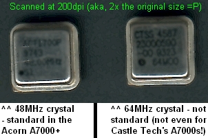
An 8-pin (half-size, square-shaped), 5 volt (NOT 3.3 volt) crystal oscillator module that's faster than 48MHz. These actually have four pins, but are always referred to as eight-pin modules.
Availability: Maplin stores stock the sockets, but have discontinued selling all oscillators. So, to get those, try an online retailer like Rapid Electronics or RS. Both stock clocks up to 80MHz and beyond (when I last checked). Otherwise, 64MHz ones can be found on old ISA Token Ring network cards (I've seen them on models from Madge and Infineon), just grab one and you'll be sorted. Other random PCBs might also have high-speed oscillators onboard - if you're desperate, hunting around at car boot sales might yield some stuff.
How fast can you go?
From reading the Cirrus Logic PS7500FE manual (the A7000+ uses most of the parts from this development board), the MAXIMUM speed of oscillator you can put in is 80MHz. Can it go higher? Sadly, it can't - I tried with a proper 80MHz oscillator, and the machine turned on OK, but refused to boot up. Perhaps a jumper needs to be removed or soldered in somewhere, but it'd be difficult to locate it - for me, anyway, as I'm reasonably good at soldering and figuring things out, but electrical engineering isn't my top skill :P
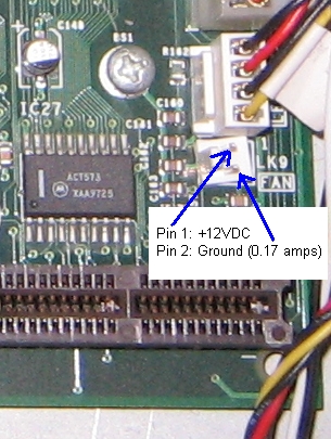
If it is possible to hit 80MHz, extra cooling shouldn't be needed - at least, nothing was mentioned in the PS7500FE manual. There is, however, a two-pin connector marked FAN on the
A7000+ board, where you can plug in a 12V fan if you want - just make sure it doesn't draw more than 0.2A of current.
Procedure
-
Open up your Acorn A7000+. It's held together with standard cross-head screws, so no funny bits are required. First, undo the two screws at the back of the machine, then lift it off. You should now be able to lift up the lid (the front bezel is attached to this) and get inside it. Next, look at the exposed front of the machine, and undo the two screws holding in the FDD + HDD + CD drive rack. Very carefully lift up this big rack (detatch the IDE + floppy + power cables once you can reach them) and put it somewhere out of the way.
-
You'll need to get the motherboard out as well. Undo the two screws on the motherboard (if you've filled up the EDO RAM slot, one of them will be covered over by it, so remove this first), then undo all six of the thumbscrews at the rear (2 of each are on the serial, parallel and VGA ports) and unplug any cables connected to the motherboard. Don't worry about all the power cables and such - all of them are notched somehow, so you can't plug them in the wrong way round.
-
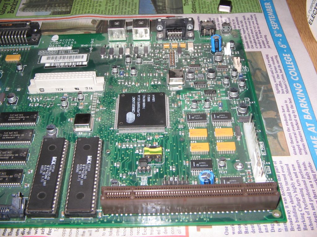
Take out the board, and put it ready near your soldering iron and other tools. Desolder the 48MHz crystal oscillator that drives the CPU (it's South of the PS7500FE). Flip the board over and locate the four solder joints holding it, then tape over all the tracks running near them to prevent possible damage. Place the desoldering braid over the joint and press the iron to the joint to suck away the solder - eventually you will expose the holes where the oscillator's legs come through the board.
-
Once all the solder is gone from the holes, you'll need to remove the oscillator. Ideally, strong plastic grabbing tongs should be used. Don't use a knife - I used one to lever it out, but scratched one of the tracks running through the PCB underneath the oscillator, which thankfully wasn't fatal. If you do use a knife, make sure it's a non-serrated one, e.g. for spreading butter. Take your time with this stage - screwing up is not an option!
-
Once the 48MHz oscillator is out, get your DIL socket and modify it to fit in the 4 holes left from where the oscillator was in the board. Simply bend (don't break!) the middle pins up so that they are resting against the sides of the socket, and that one pin at each corner is left alone. Then carefully wrap some electrical / insulation tape around the bent pins to secure them to the socket. Make sure the four corner pins, and their respective corner holes, are not covered up or bent.
-
Solder in your socket - make sure the notch in the socket is facing the South of the board (check with the onboard compass image - it's between the parallel port and a PS/2 port). Again, make sure tracking on the underside of the PCB around the oscillator holes are protected with electrical tape. Note that massive blobs of solder are not necessary to hold the socket in place - just make SURE the new joints aren't loose, or you could run into serious poblems later on.
-
Optional stage: if you also want to desolder and socket the RAM clock oscillator (in the A7000+ it's 64MHz, located West of the PS7500FE), do it after you've tested and ensured the first socket is OK - or if you're confident enough at being able to remove two oscillators and put sockets in place in one sitting, carry it out now.
-
You should now be at the stage shown in this photo. All you need to do now is plug in your new oscillator, making SURE pin 1 (indicated by the sharp corner and the black dot on it) is aligned to the beveled / cut-off corner marked in white on the PCB by the socket (you can see it clearly in the previous photo).
-
Put it all back together, making sure everything is plugged in / screwed in as it was before. Power up, and see if it works. Typically, the best way to compare the performance boost is to play some MP3s (over 96kbps) - this is where the overclock seems to make quite a difference. It probably makes a change in other areas, though, I just haven't checked yet. If you're interested, my results can be found here.
Boring Copyright Stuff
Unless otherwise stated, all of this information was written by Rob Watts (aka RobbyW / STC-Fan / zedeckseightyone) ©2004-2008, or adapted from sources who have helpfully contributed information to this document. You may NOT use any information from this document unless you ask nicely beforehand, or something like that.